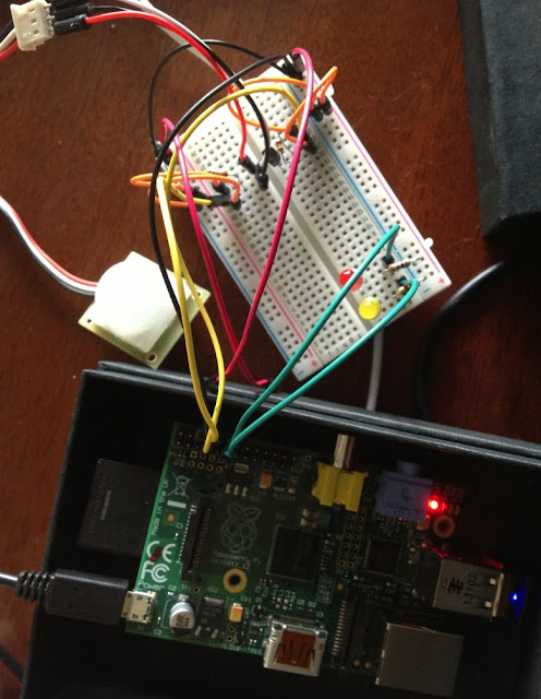
Below are the links to the actual parts I used. Eventually these links may stop working, but all the parts are very common and easily obtainable.
- Yellow LED
- Red LED
- Breadboard
- Jumper wires M/M
- Jumper wires M/F
- Two 100 Ohm resistors
- One 4.7k Ohm resistor
- One 10k Ohm resistor
- DS18B20 digital temperature sensor
- SparkFun SE-10 PIR motion sensor
Here is the circuit
The big red square are Raspberry Pi (Model B) pins. The pins differ on Model A. Two smaller red squares are sensors - temperature and motion. Four tiny red squares are resistors. Plus two diodes (LEDs). Green lines are wires and green dots are wire junctions. Wire properly and it should work.
Calculating LED resistor: why 100 Ohm?
Ohm's Law: I = V / R → R = V / I
- I is the current measured in amperes, V is the voltage measured in volts, R is the resistance measured in ohms.
R = 3.3 / 0.012 = 275 Ohm
Oh, the LED itself acts as a resistor of approximately 175 Ohm (measured manually), thus:
R = 275 - 175 = 100 Ohm
So, if we put a 100 Ohm resistor in a circuit with one LED, the current in the entire circuit will be 12 mAmps.
Pull-up resistor
A pull-up resistor connects sensor's power terminal with data terminal. Read more about pull-up resistors here. One sensor in the circuit is using 4.7k Ohm and another is using 10k Ohm pull-ups.
Wiring sensors and LEDs
Read manufacturer's data sheet to understand which of the sensor's terminals connects to power, data and ground. E.g. on my motion sensor the white wire was ground and the black wire was alarm (data).
To wire and enable DS18B20 temperature sensor please use this guide. Follow the guide and the sensor will be connected to the GPIO4 pin exactly as on my circuit. Here is the data sheet.
Motion sensor connects in the similar manner to GPIO14 and uses 5V. It will send data directly to the GPIO14 pin. Here is the data sheet.
Wiring a LED is pretty simple but you may use this guide, it has pictures!
Python program
It checks room temperature every half a second and lights up one LED when the temperature is above 20 C (just breath on the sensor). Lights up another LED when it detects motion. You may want to alter the temperature limit ans change the device directory (mine is 28-0000047b16ad) in the source code. Download link.
And finally, a pretty picture
In my next post I will assemble the same circuit using Pi-Face.


Hey, nice site you have here! Keep up the excellent work! Pir Motion Sensor|Pir Sensor|Motion Detector
ReplyDelete